My ECG
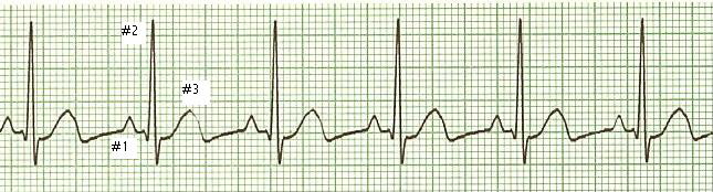
Another ECG I've seen - mine has a negative spike that's just too big.
The Story of My ECG
Page: 6 is the loneliest number
Deep thoughts...by Jack Handey
|
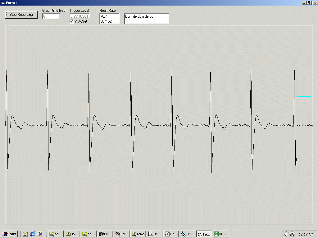
My ECG |
Another ECG I've seen - mine has a negative spike that's just too big. |
Everything seems to work properly. The peaks come when I can feel my pulse. The heart rate seems to be calculating correctly. It even auto triggers in case the amplitude of the signal is not very high. As far as I can tell, there isn't a major problem. Some people may be concerned that my graph has a negative peak. At first, I was too, but after many much smarter people told me that the negative peaks are normal, I just wrote myself off as stupid. However, there are a few problems with my ECG. The T-wave (peak #3) is a little distorted. This is due to the minimum bandwidth of my sound card. My Soundblaster is spec'ed to be around 10Hz min. When I toggle an input low/high, you can see the effects of the minimum bandwidth.
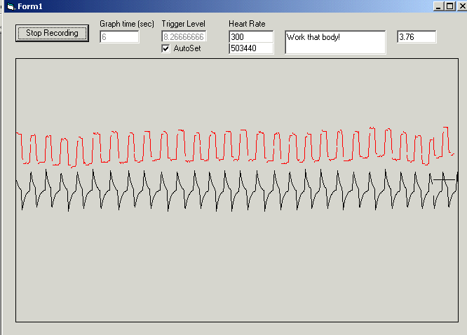
Black line is the output with a square wave input (about 4.5Hz) Red line is after signal processing the output. |
The black line is the output of my ECG with a square wave input (switched by an intricate device called "the hand" pulling in and out a wire). Anyways, the output should be pretty close to a square wave. So I decided to do a little real-time signal processing and came up with a routine that would filter out the effect of the low frequency cutoff. The red line is the output after the black line has been run through my routine. As you can see, the output is much closer to a square wave input. It's not perfect, but it makes it a lot better.
Long story short, after running with the new filtered output, the ECG looked a little better. There were a few places that got more squared up, but overall, the effects weren't worth mentioning. When I thought more about it, I figured that everyone's sound card is different, so I removed my little signal processing routine and decided to leave it as is.
So now you may be asking me: what in the world would anyone do with this? For one, someone could monitor themselves so they don't die from over gaming. Or perhaps someone could learn the way of the Jedi, and alter their heartbeat. Maybe someone keeps being told they don't have a heart. This tool could be used to prove them wrong. This ECG would be perfect to see if your heart is still beating. And if it stops, you know to call 911. There are millions of things someone could do with this. It's all up to the imagination.
Here's a few of my favorites given to me by some good people: Go to the local hospital and see if the ECG matches a 'real' ECG. Use it with other stuff to make a lie detector. See if the heartbeats of two people sleeping close together really do synchronize. Use it to pick up women!
That's cool. Why don't you manufacture these and sell them?
I would never dream of selling these as is. For one, this circuit has absolutely no isolation to the digital interface (the computer). With the risk of electrocuting a patient, I would guess hospitals don't want to buy something that's not UL listed or gone through the FDA. Another reason is the accuracy. Somehow I think my ECG isn't accurate enough for hospital use. And consumers? If the consumer got a hold of an ECG, what would they do with it? Would you know how to read an ECG and tell if there was a problem with your heart? I personally don't see a lot of use except for the hobbyist who knows what they are doing.
Now what?
I'm still kind of tempted to improve upon my design or my program. Especially the isolation with the digital portion. I might put in that analog-to-digital converter, then read the data (rather than remove the effect of the sound card via mathematical formulas). I may even be able to adapt this project so it works with a PDA. Oooo, better yet, I could put in a defibrillator circuit! Well, maybe not that one. I may feel safe probing my body for electrical signals, but I'm not comfortable applying large voltages to it. But, if someone wants to be my guinea pig, I'll be happy to zap them. (I'll of course make you sign a release form).
Unfortunately, due to financial constraints, I need to put this project on the back burner. (Hey, I need to start earning money again!) I am happy that I succeeded in fulfilling my constraints. Considering how I had most of the parts on hand, the total cost to me was about $0.58. (That's $0.55 for the 5 foot wire and $0.03 for the three pennies I had to solder to). Of course, for people starting from scratch, it will cost them around $4. My second constraint on ease of building was also accomplished. The project uses a simple 9V battery, a bunch of resistors, some caps, and some LF353 op-amps. Considering how everything was just a 5% tolerance component, I don't think there is any fine tuning that needs to be done. The circuit should automagically set all of the right bias points and work.
I hope everyone enjoyed my little project, and thanks for visiting!